Acoustophoretic Assembly: Moving Small Objects with Sound

The acoustic radiation force is a nonlinear wave effect that exerts a non-zero time-averaged force on objects in the wave. Using the acoustic radiation force to manipulate objects and small particles is called acoustophoresis and has been widely explored for applications range from moving a few objects at a time, to acting on a continuous flow of particles, to arranging many particles into patterns. In particular, acoustophoretic assembly of embedded particles into pre-determined patterns provides many opportunities for advanced manufacturing and 3D printing of composite materials.
There are three key considerations in applying acoustophoretic assembly to manufacturing: 1) the particle pattern geometries that can be created, 2) the quality of the final pattern, and 3) the time required to make the pattern. The ability to create arbitrary user-defined particle geometries has been achieved in the literature using acoustic transducer arrays. However, the final pattern quality is often only evaluated qualitatively, and there has been much less work towards understanding how much time is required to form the assembly.
My PhD research focused on understanding and modeling the acoustophoretic assembly process to address the questions of pattern quality and the time required. I proposed thinking of the assembly process as a change in local particle concentration, and used mass-transfer principles to derive an analytical expression for the local concentration profile in planar standing waves. The analysis also yielded a time constant for pattern formation. Additionally, I developed a method of creating more complex pattern geometries in a single-transducer setup by applying multiple wave frequencies in sequence. Along the way, I built experimental setups and wrote Matlab code to measure the absolute magnitude of the acoustic radiation force with particle tracking, which provided experimental validation for my models.
For additional information, see:
- Y. J. Wang, L. A. Chai, R. E. Zubajlo, and B. W. Anthony, “Sequencing waves in single-transducer acoustophoretic patterning of microspheres,” Applied Physics Letter 121, 244106 (2022) https://doi.org/10.1063/5.0112113
- My PhD thesis: “Formation Process of Acoustophoretic Patterns” https://dspace.mit.edu/handle/1721.1/143380
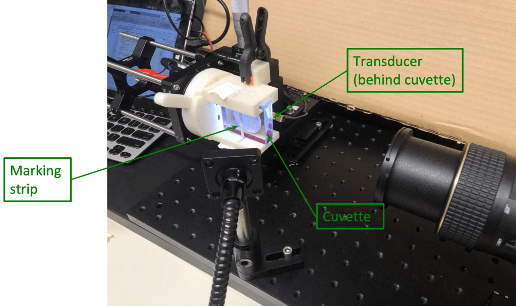


Schematic of the patterning device and annotated sample image from the camera.

Close-up of the cuvette, transducer, and mount in a later version of my setup. I have made the marking strip more robust and added a camera rail to allow more fine adjustments of the camera position. Clamps have been replaced with zip ties to hold the transducer more securely.
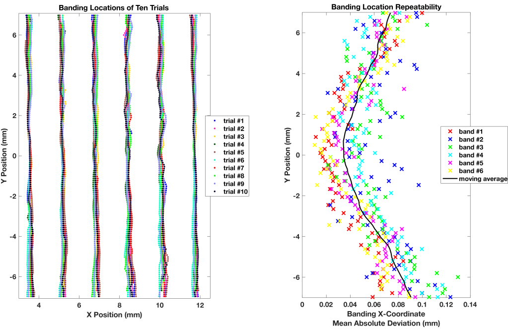
The pattern geometries made using acoustophoresis are repeatable. Repeatability at the center of the cuvette is better than at the top and bottom, likely due to acoustic streaming that disrupt the pattern.
The quality of the acoustophoretic pattern depends on the time and the strength of the acoustic wave, measured here as transducer peak-to-peak driving voltage. A weaker wave applied for a longer amount of time can achieve similar results as a stronger wave applied for less time.


The magnitude of the acoustic radiation force on the microspheres depends on the transducer driving frequency, and needs to be measured experimentally. The peaks correspond to the resonant frequencies of the device.
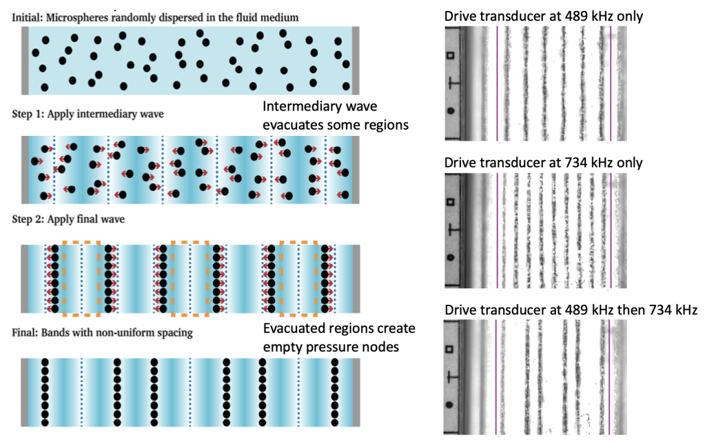
By applying two frequency in sequence, I was able to create microsphere patterns that are not otherwise possible with a single transducer.